จากข้อมูลด้านบนเราสามารถนำข้อมูลที่ได้มานั้นมาประยุกต์ใช้งานได้ในรูปแบบอื่นๆ ได้ต่อไป ในบทความนี้เราจะนำข้อมูลไปทำการเขียนโปรแกรมควบคุมรถให้ทำการติดตามวัตถุที่เราต้องการ
เขียนโค้ดโปรแกรมดังนี้
#include <SPI.h>
#include <Pixy.h>

#define X_CENTER 160L
#define Y_CENTER 100L
#define RCS_MIN_POS 0L
#define RCS_MAX_POS 1000L
#define RCS_CENTER_POS ((RCS_MAX_POS-RCS_MIN_POS)/2)

#define Forward 1
#define Backward 0

#define MOTOR_A 0
#define MOTOR_B 1

const byte PWMA = 3; // PWM control (speed) for motor A
const byte PWMB = 11; // PWM control (speed) for motor B
const byte DIRA = 12; // Direction control for motor A
const byte DIRB = 13; // Direction control for motor B
ในส่วนแรกเป็นส่วนที่เราเรียกใช้ Library และกำหนดค่าเริ่มต้นต่างๆ ที่จำเป็นต้องใช้ในโปรแกรมรวมไปถึงขาที่ใช้เชื่อมต่อ โดยในที่นี้เราจะเรียกใช้ Library ด้วยกัน 2 ส่วน คือ ส่วนของ SPI และ Pixy หลังจากนั้นทำการกำหนดค่าและขาต่างๆ ที่นำไปใช้งาน
//---------------------------------------
// Servo Loop Class
// A Proportional/Derivative feedback
// loop for pan/tilt servo tracking of
// blocks.
// (Based on Pixy CMUcam5 example code)
//---------------------------------------
class ServoLoop
{
public:
    ServoLoop(int32_t proportionalGain, int32_t derivativeGain);

    void update(int32_t error);

    int32_t m_pos;
    int32_t m_prevError;
    int32_t m_proportionalGain;
    int32_t m_derivativeGain;
};

// ServoLoop Constructor
ServoLoop::ServoLoop(int32_t proportionalGain, int32_t derivativeGain)
{
    m_pos = RCS_CENTER_POS;
    m_proportionalGain = proportionalGain;
    m_derivativeGain = derivativeGain;

    m_prevError = 0x80000000L;
}

// ServoLoop Update
// Calculates new output based on the measured
// error and the current state.
void ServoLoop::update(int32_t error)
{
    long int velocity;
    char buf[32];
    if (m_prevError!=0x80000000)
    {
        velocity = (error*m_proportionalGain + (error - m_prevError)*m_derivativeGain)>>10;

        m_pos += velocity;
        if (m_pos>RCS_MAX_POS)
        {
            m_pos = RCS_MAX_POS;
        }
        else if (m_pos<RCS_MIN_POS)
        {
            m_pos = RCS_MIN_POS;
        }
    }
    m_prevError = error;
}
// End Servo Loop Class
//---------------------------------------
ส่วนต่อมาคือส่วนที่ใช้ในการควบคุม Servo เป็นส่วนที่ใช้ในการคำณวนและควบคุมตำแหน่งของ Servo สามารถดูข้อมูลได้ที่ Example > Pixy > pantilt?
Pixy pixy;  // Declare the camera object

ServoLoop panLoop(200, 200);  // Servo loop for pan
ServoLoop tiltLoop(200, 200); // Servo loop for tilt
ในส่วนนี้เป็นประกาศชื่อ Object เข้ากับ Library และกำหนดขอบเขตการ Pan Servo
//---------------------------------------
// Setup - runs once at startup
//---------------------------------------
void setup()
{
    Serial.begin(9600);
    Serial.print("Starting...\n");
    pixy.init();
      setupArdumoto(); //ฟังก์ชั่นกำหนด Pin และโหมดการทำงานของ Motor
}
ส่วนของ Setup เป็นส่วนที่ใช้ในกำหนดการทำงานต่างๆ เช่น กำหนดโหมดการทำงานให้เป็น Input/output เป็นต้น พร้อมทั้งสั่งเริ่มต้นการทำงาน?
uint32_t lastBlockTime = 0;
//---------------------------------------
// Main loop - runs continuously after setup
//---------------------------------------
void loop()
{
    uint16_t blocks;
    blocks = pixy.getBlocks();

    // If we have blocks in sight, track and follow them
    if (blocks)
    {
        int trackedBlock = TrackBlock(blocks);
          FollowBlock(trackedBlock);
        lastBlockTime = millis();
    }
    else if (millis() - lastBlockTime > 100)
    {
            stopArdumoto(MOTOR_A);
            stopArdumoto(MOTOR_B);
        ScanForBlocks();
    }
}
ในส่วนของ Loop เป็นส่วนในการทำงานวนซ้ำแบบไม่รู้จบ เราเขียนโปรแกรมในส่วนที่ต้องการทำงานวนซ้ำไว้ในส่วนนี้หรือเรียกว่าส่วน Main ของโปรแกรมก็ว่าได้ จากโปรแกรมนี้จะทำการอ่านค่าจากกล้อง นำข้อมูลที่ได้ส่งไปยังฟังก์ชั่นในการติดตามวัตถุเมื่อพบสิ่งที่ต้องการ แต่ถ้าไม่พบจะทำการเรียกฟังก์ชั่น Scan หาต่อไป?
int oldX, oldY, oldSignature;

//---------------------------------------
// Track blocks via the Pixy pan/tilt mech
// (based in part on Pixy CMUcam5 pantilt example)
//---------------------------------------
int TrackBlock(int blockCount)
{
    int trackedBlock = 0;
    long maxSize = 0;
    Serial.print("blocks =");
    Serial.println(blockCount);
    for (int n = 0; n < blockCount; n++)
    {
        if ((oldSignature == 0) || (pixy.blocks[n].signature == oldSignature))
        {
            long newSize = pixy.blocks[n].height * pixy.blocks[n].width;
            if (newSize > maxSize)
            {
                trackedBlock = n;
                maxSize = newSize;
            }
        }
    }
    int32_t panError = X_CENTER - pixy.blocks[trackedBlock].x;
    int32_t tiltError = pixy.blocks[trackedBlock].y - Y_CENTER;
    panLoop.update(panError);
    tiltLoop.update(tiltError);
    pixy.setServos(panLoop.m_pos, tiltLoop.m_pos);
    oldX = pixy.blocks[trackedBlock].x;
    oldY = pixy.blocks[trackedBlock].y;
    oldSignature = pixy.blocks[trackedBlock].signature;
    return trackedBlock;
}
ฟังก์ชั่นในการตรวจสอบวัตถุ เป็นฟังก์ชั่นที่รับข้อมูลมาจากฟังก์ชั่น main และนำข้อมูลที่ได้มาทำการตรวจสอบว่าข้อมูลที่ได้รับมานั้นมีอะไรบ้าง หลังจากตรวจสอบก็ทำการคำนวณและส่งข้อมูลไปยังฟังก์ชั่นในการควบคุม Servo และมอเตอร์ขับเคลื่อนต่อไป?
//---------------------------------------
// Follow blocks
// This code makes the robot base turn
// and move to follow the pan/tilt tracking
// of the head.
//---------------------------------------
int32_t size = 500;
void FollowBlock(int trackedBlock)
{
    int32_t followError = RCS_CENTER_POS - panLoop.m_pos;  // How far off-center are we looking now?

    // Size is the area of the object.
    // We keep a running average of the last 8.
    size += pixy.blocks[trackedBlock].width * pixy.blocks[trackedBlock].height;
    size -= size >> 3;

    // Forward speed decreases as we approach the object (size is larger)
    int forwardSpeed = constrain(500 - (size/256), -250, 250);

    // Steering differential is proportional to the error times the forward speed
    int32_t differential = (followError + (followError * forwardSpeed))>>8;

    // Adjust the left and right speeds by the steering differential.
    int leftSpeed = constrain(forwardSpeed + differential, -250, 250);
    int rightSpeed = constrain(forwardSpeed - differential, -250, 250);
    // And set the motor speeds
        if(leftSpeed > 0)
        {
          driveArdumoto(MOTOR_A, Backward, leftSpeed);
        }
        if(rightSpeed > 0)
        {
          driveArdumoto(MOTOR_B, Backward, rightSpeed);
        }
        if(leftSpeed < 0)
        {
          driveArdumoto(MOTOR_A, Forward, (leftSpeed*-1));
        }
        if(rightSpeed < 0)
        {
          driveArdumoto(MOTOR_B, Forward, (rightSpeed*-1));
        }
}
ฟังก์ชั่นในการติดตาม เป็นฟังก์ชั่นที่รับข้อมูลมาจากฟังก์ชั่นตรวจสอบวัตถุและนำข้อมูลที่ได้มาทำการคำนวณขนาด พร้อมทั้งเปรียบเทียบค่าต่างๆที่นำไปสั่งงานมอเตอร์หรือบอร์ดไดร์ฟเพื่อใช้งานการขับเคลื่อนรถให้ติดตามวัตถุ
//---------------------------------------
// Random search for blocks
//
// This code pans back and forth at random
// until a block is detected
//---------------------------------------
int scanIncrement = (RCS_MAX_POS - RCS_MIN_POS) / 150;
uint32_t lastMove = 0;

void ScanForBlocks()
{
    if (millis() - lastMove > 20)
    {
        lastMove = millis();
        panLoop.m_pos += scanIncrement;
        if ((panLoop.m_pos >= RCS_MAX_POS)||(panLoop.m_pos <= RCS_MIN_POS))
        {
            tiltLoop.m_pos = random(RCS_MAX_POS * 0.6, RCS_MAX_POS);
            scanIncrement = -scanIncrement;
            if (scanIncrement < 0)
            {
                                driveArdumoto(MOTOR_A, Backward, 150);
                                driveArdumoto(MOTOR_B, Forward, 150);
            }
            else
            {
                                driveArdumoto(MOTOR_A, Forward, 150);
                                driveArdumoto(MOTOR_B, Backward, 150);
            }
            delay(random(250, 500));
        }

        pixy.setServos(panLoop.m_pos, tiltLoop.m_pos);
    }
}
ฟังก์ชั่นในการค้นหาวัตถุ เป็นฟังก์ชั่นที่ใช้ในการสั่งงาน Servo และมอเตอร์เมื่อไม่พบวัตถุจะทำการสุ่มการเคลื่อนไหวและเคลื่อนที่เพื่อตรวจหาวัตถุที่ต้องการต่อไป
void driveArdumoto(byte motor, byte dir, byte spd)
{
  if (motor == MOTOR_A)
  {
    digitalWrite(DIRA, dir);
    analogWrite(PWMA, spd);
  }
  else if (motor == MOTOR_B)
  {
    digitalWrite(DIRB, dir);
    analogWrite(PWMB, spd);
  }
}
ฟังก์ชั่นควบคุมบอร์ดไดร์ฟหรือมอเตอร์ เป็นฟังก์ชั่นที่ใช้ในการสั่งงานและควบคุมความเร็วของมอเตอร์
void stopArdumoto(byte motor)

{
  driveArdumoto(motor, 0, 0);
}
ฟังก์ชั่นที่ใช้ในการหยุดมอเตอร์
void setupArdumoto()
{
  // All pins should be setup as outputs:
  pinMode(PWMA, OUTPUT);
  pinMode(PWMB, OUTPUT);
  pinMode(DIRA, OUTPUT);
  pinMode(DIRB, OUTPUT);

  // Initialize all pins as low:
  digitalWrite(PWMA, LOW);
  digitalWrite(PWMB, LOW);
  digitalWrite(DIRA, LOW);
  digitalWrite(DIRB, LOW);
}
ฟังก์ชั่นที่ใช้ในการกำหนดขาและโหมดในการทำงานของส่วนที่ใช้ในการควบคุมมอเตอร์
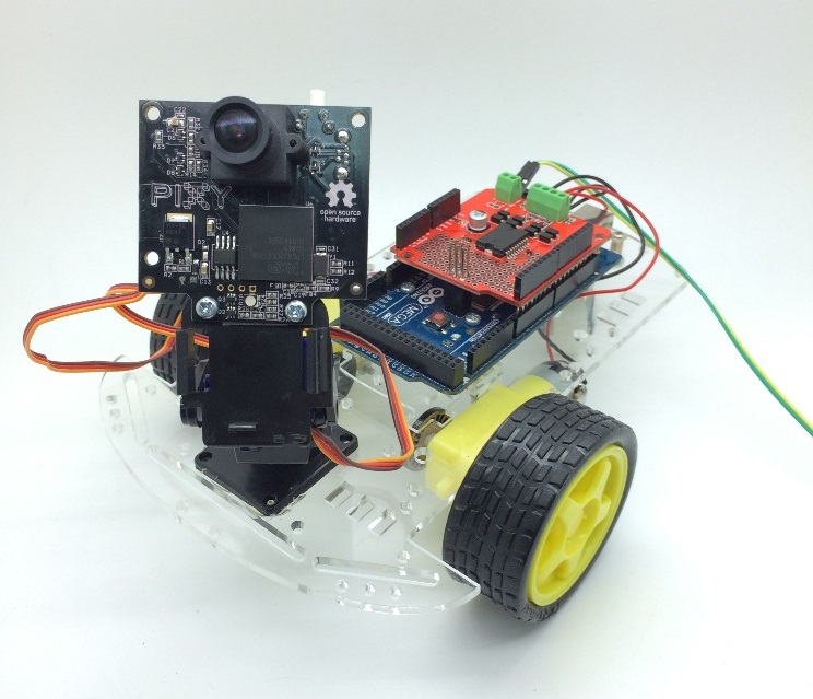
วิธีการทดสอบ
ให้ทำการประกอบส่วนต่างๆเข้าด้วยกันดังนี้
1. ประกอบโครงรถ
2. นำ Shield Motor L298 ต่อเข้ากับ Arduino Mega2560
3. ต่อมอเตอร์ล้อขวาต่อเข้ากับ Shield ทางช่อง Motor A
4. ต่อมอเตอร์ล้อซ้ายต่อเข้ากับ Shield ทางช่อง Motor B
5. ต่อกล้อง Pixy + ขาตั้ง เข้ากับ Arduino Mega2560 ทางพอร์ต ICSP ดังภาด้านล่าง
จากโค้ดด้านบนเราจะเห็นได้ว่าการทำงานของโค้ดนี้คือ เมื่อทำการ Set signature ที่ต้องการตัวกล้อง Pixy นั้นจะส่งข้อมูลออกมาก็ต่อเมื่อมีการเรียกใช้ข้อมูล เมื่อได้ข้อมูลมานั้นเราต้องทำการตรวจสอบเพื่อหาขนาดและตำแหน่งของวัตถุที่พบ พร้อมทั้งสั่งงานให้ส่วนของ Servo และมอเตอร์ให้เคลื่อนที่ตามที่ได้รับข้อมูลมา
วิธีการทดสอบ ให้ทำการอัพโหลดโค้ดด้านบนไปยัง Arduino Mega2560 พร้อมทั้งเชื่อมต่อกล้องไปยังคอมพิวเตอร์และเปิดโปรแกรม PixyMon หลังจากนั้นทำการ Set signature และเลือกไปที่เมนู Run default program เมื่อกล้องทำงานให้ทำการถอดสายกล้องและ Arduino ออก พร้อมทั้งหาแหล่งจ่ายไฟมาจ่ายเข้ายังช่องด้านบนของ Shield ตัวรถก็พร้อมทำงาน ดูวิธีการได้จาก VDO ด้านล่าง
แหล่งที่มาและอ้างอิงข้อมูล
1. http://www.cmucam.org/projects/cmucam5/wiki
2. https://learn.adafruit.com/pixy-pet-robot-color-vision-follower-using-pixycam/overview